Front Low-Voltage Landscape Lighting Installation
- Manufacturer
- Hampton Bay
- Planned church use
- Tentatively March–April 2027
The March–April 2027 window is a planning estimate, not a fixed installation date.
Purpose
This Guide preserves operating, installation, wiring, photocell, cable-selection, troubleshooting, and fixture information for the planned low-voltage landscape-lighting system at the front of the church.
The current source set consists of nine photographs of Hampton Bay documentation. The photographs remain the authoritative source. The illustrations in this Guide are cropped, contrast-adjusted derivatives made from those photographs for easier reading.
Scope
This Guide covers the planned front-of-church low-voltage exterior and landscape lighting.
It does not cover sanctuary service lighting, stage lighting, or lighting controlled through Onyx or Companion.
Source documentation currently identified
The photographed documentation includes:
- Hampton Bay Quick Reference Guide for Slimline and Metal transformer series
- Hampton Bay transformer Use and Care material
- Hampton Bay Low Voltage Flood Light 4-Pack
- Flood-light model
IWH1501L-4PK - Item
1001 488 412
The exact Hampton Bay transformer model intended for the church has not yet been identified.
Transformer families shown in the source
The Quick Reference Guide shows both Slimline and Metal transformer families.
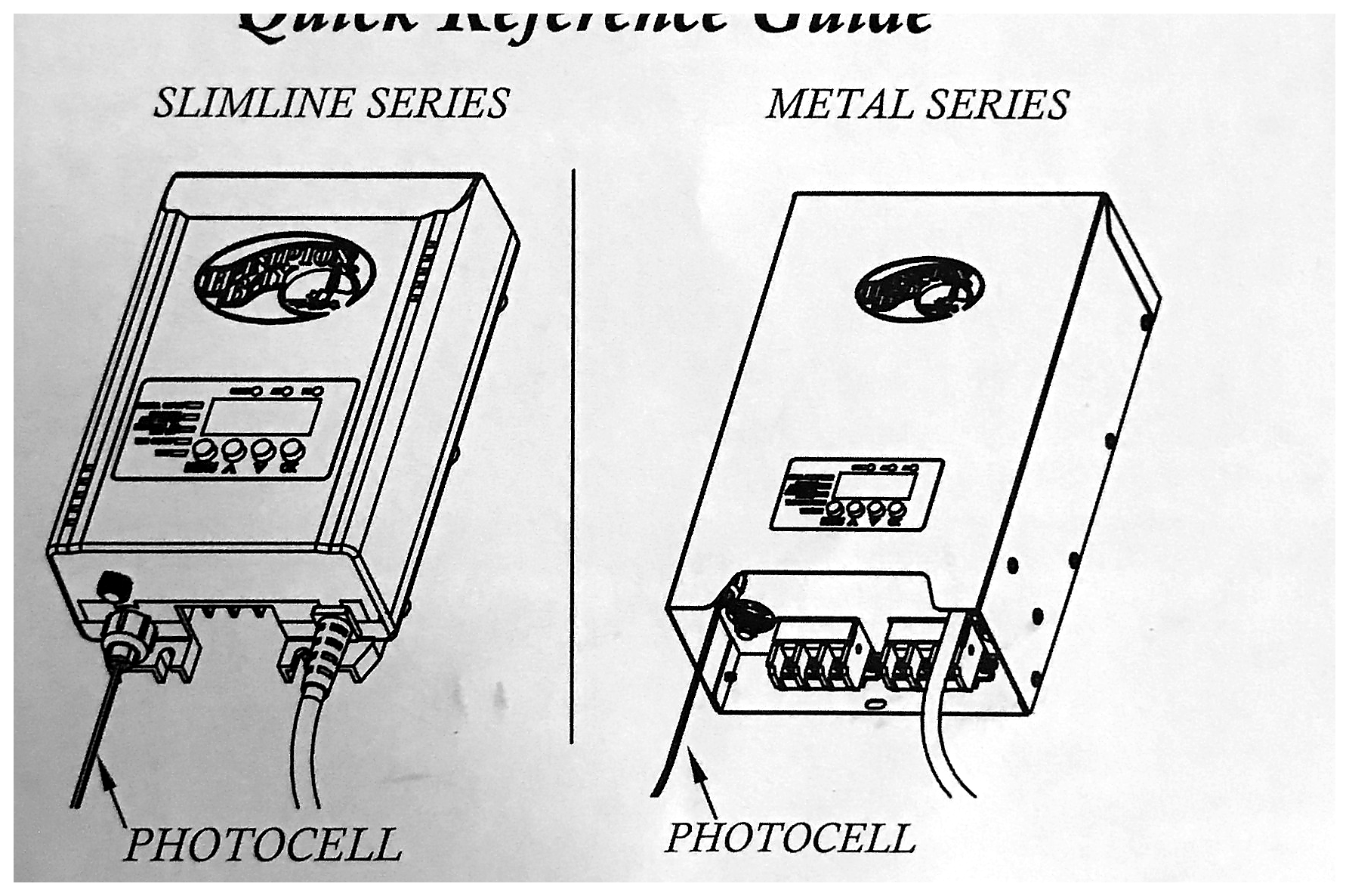
The source set does not establish which transformer family will be used at the church. Verify the installed or purchased transformer label before recording the model here.
Photocell operation
The documentation describes photocell-controlled automatic operation as the factory-default mode. With the photocell connected, the system can turn the landscape lights on at night and off during daylight.
The source strongly emphasizes connecting the photocell before configuring the transformer.
Photocell mounting
Mount the photocell bracket to a solid surface, protect the cable from lawn equipment, and avoid aiming the sensor toward nighttime light sources such as windows, porch lights, or streetlights.
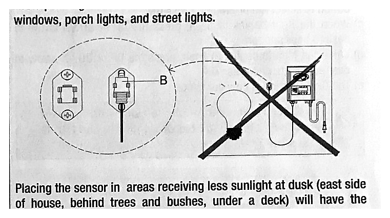
A darker location causes the transformer to respond earlier in the evening; a brighter location delays turn-on. Final photocell position and orientation should therefore be adjusted to the desired dusk level.
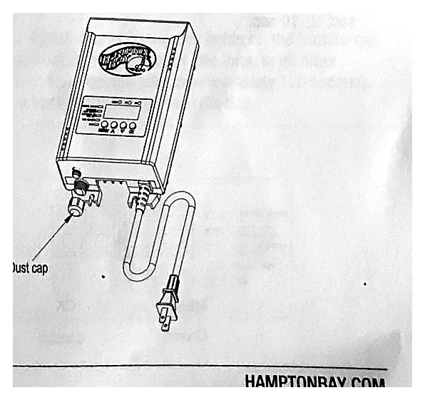
If no photocell is connected, the documentation shows a dust cap for the connector opening.
Operating modes
Manual On/Off
The transformer provides a manual mode selected with the MENU control. In that mode the arrow controls can be used to switch the landscape lights on or off.
Photocell Auto On/Off
Photocell Auto On/Off is shown as the default factory mode. When selected and confirmed, the photocell controls dusk-to-dawn operation.
Time On/Off
The transformer also supports scheduled ON and OFF times. The photographed quick-reference material shows setting AM/PM, hour, and minute values for both the ON and OFF time.
The source notes that the photocell is not required for Time On/Off mode and that the connector opening should be capped when the photocell is not used.
Clock setting
The photographed material shows the beginning of the clock-setting procedure but not the complete sequence. Do not rely on this Guide alone for clock programming until the missing source page is recovered or the procedure is verified from the exact transformer model.
Preparing the landscape cable
The source shows the two conductors being separated and approximately 1/2 in. (12.7 mm) of insulation removed from each conductor end.
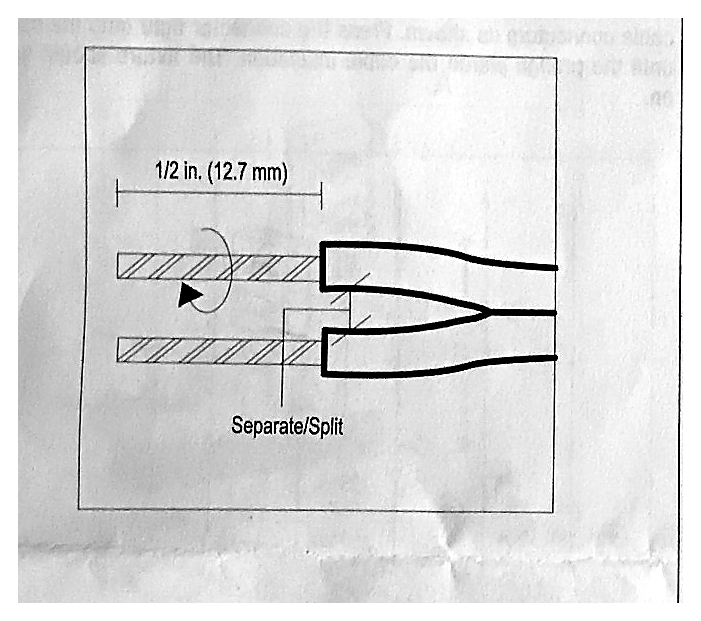
Avoid damaging or exposing conductor strands while splitting the cable.
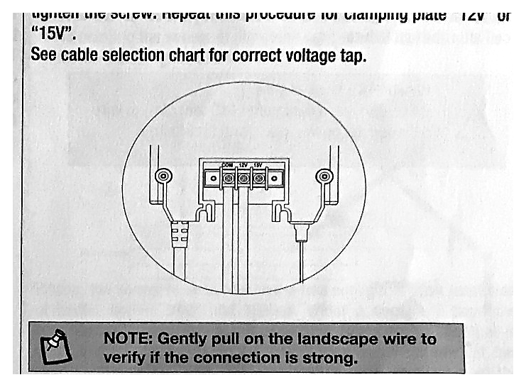
Connecting the landscape cable to the transformer
The transformer documentation shows terminals including COM, 12V, and 15V.
One conductor connects under the clamping plate at COM. The other connects to the selected
voltage tap. The correct voltage tap should be chosen using the transformer documentation and
the cable-selection guidance for the actual run.
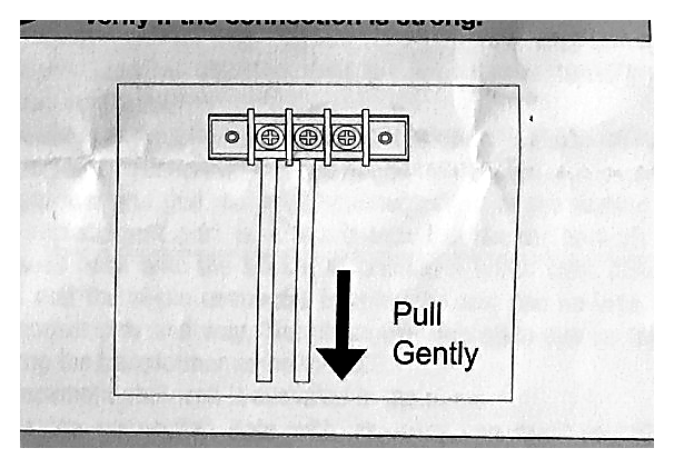
After tightening the terminal screws, gently pull the cable to confirm that the connection is secure.
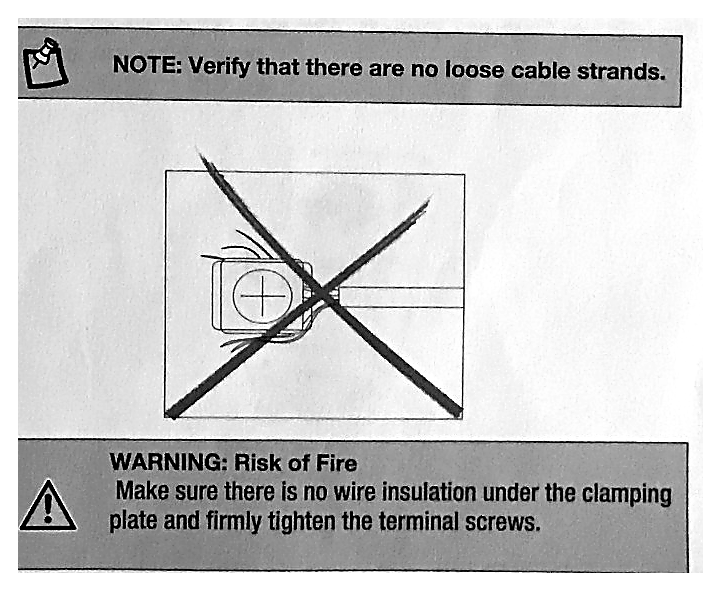
The source warns against trapping wire insulation beneath the clamping plate and against leaving loose strands.
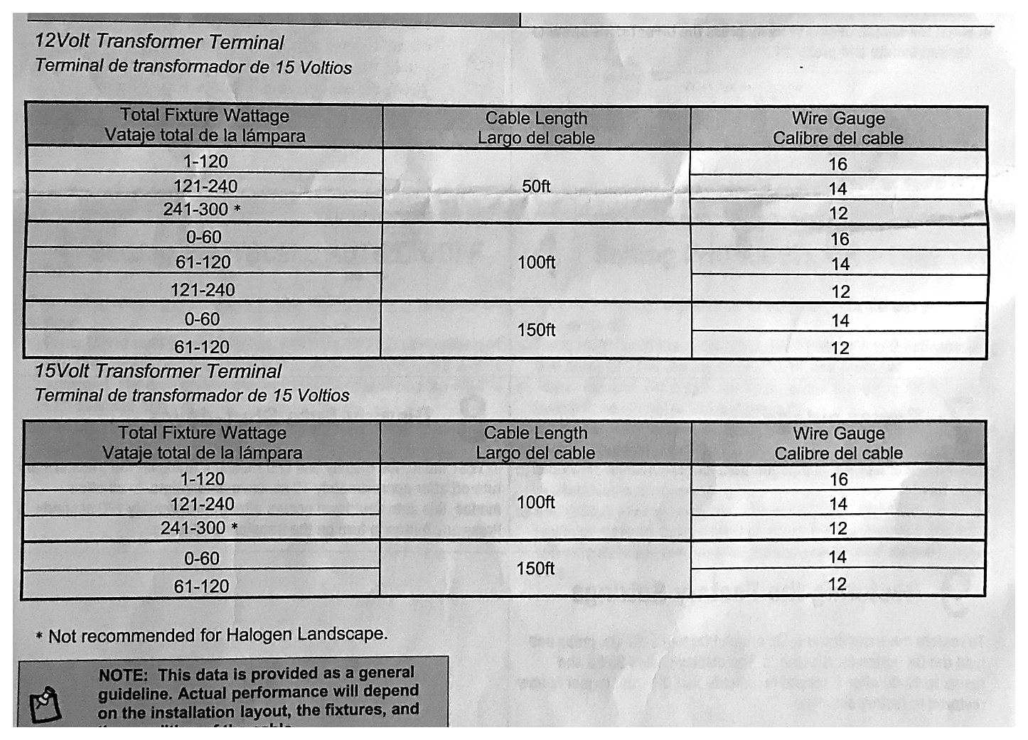
Cable selection
The transformer documentation provides a cable-selection chart based on:
- transformer voltage tap
- total fixture wattage
- cable length
- wire gauge
The photographed fixture instructions separately specify 12–16 AWG underground Low Energy Circuit Cable for the low-voltage feed.
Before installation, record the actual:
- wire gauge
- approximate cable length
- transformer voltage tap
- number of fixtures
- total connected load
Important capacity note
One photographed transformer page contains a 120-watt warning, while the general cable chart contains combinations extending to higher loads. This Guide does not resolve that difference.
Treat the exact transformer nameplate/rating as authoritative for the church installation.
Mounting the transformer
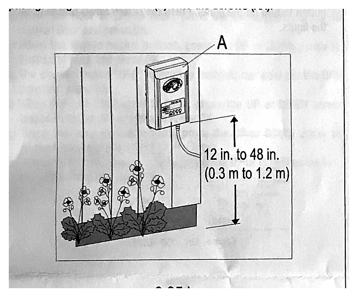
The source shows wall mounting with the transformer approximately 12–48 in. (0.3–1.2 m) above ground.
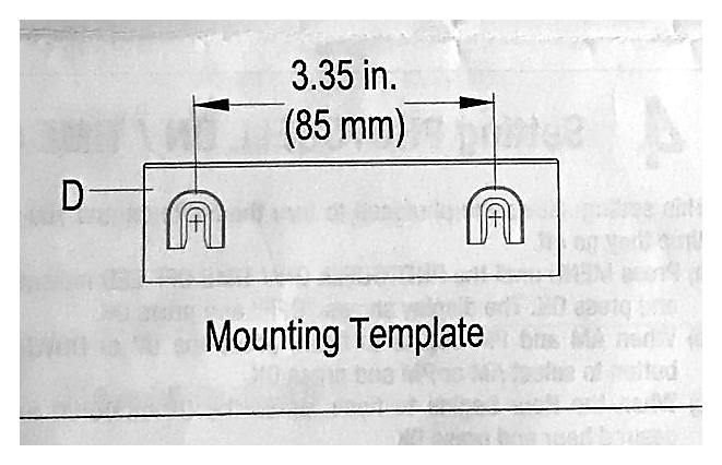
The mounting template shows approximately 3.35 in. (85 mm) between screw centers.
Record the actual mounting surface and location once the church installation is finalized.
Flood-light fixture set
The photographed fixture documentation identifies:
- Hampton Bay Low Voltage Flood Light 4-Pack
- Model:
IWH1501L-4PK - Item:
1001 488 412
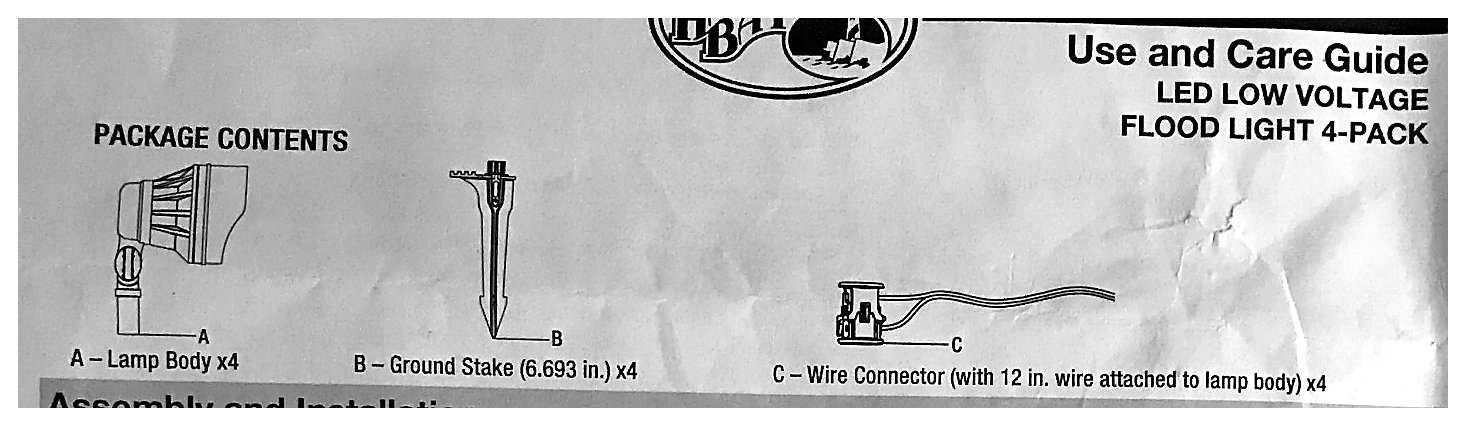
The package illustration shows:
- lamp body
- ground stake
- wire connector with a short lead attached to the lamp body
Installing and aiming a flood light
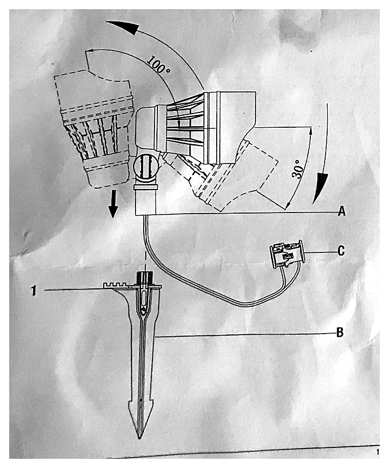
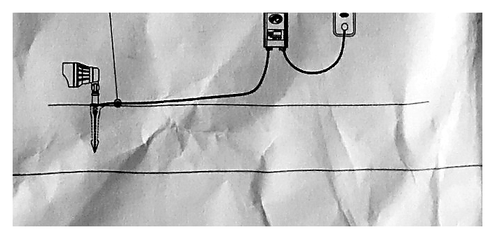
The fixture wire runs through the ground-stake assembly and the lamp body attaches to the top of the stake.
The documentation instructs the installer to prepare the hole rather than hammering the stake into the ground, and to push on the stake's foot step rather than on the lamp body.
The lamp body has a substantial vertical aiming range.
Connecting a fixture to the main landscape cable
The fixture uses a piercing connector that closes around the main low-voltage cable.
The connector's metal contacts are sharp because they pierce the cable insulation. Handle the connector by its body rather than touching the contacts.
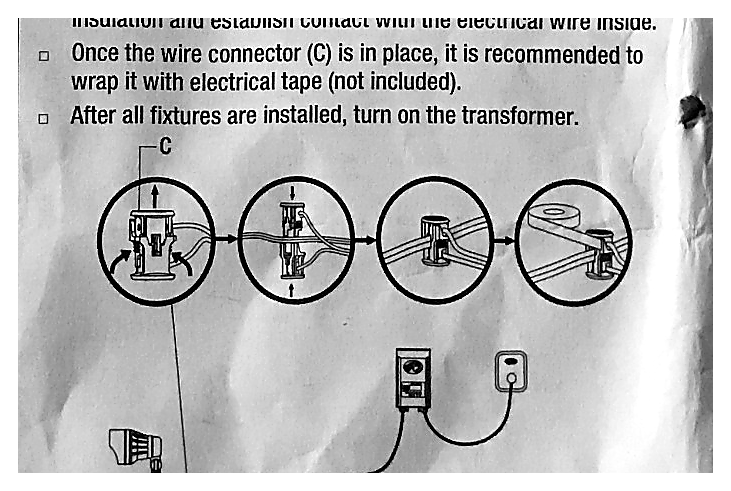
The manufacturer's illustration also shows the overall relationship between a fixture, the landscape cable, transformer, and supply connection.
The photographed fixture instructions recommend wrapping an installed connector with electrical tape.
Cable routing and burial
The source allows landscape cable and connectors to be concealed under stone or buried under grass to a maximum depth of about 6 in. (15 cm).
The transformer material also recommends leaving approximately 12 in. (30 cm) of cable beyond the final fixture.
Do not coil excess cable around the transformer.
The fixture instructions also state:
- do not install a fixture within 10 ft. of a pool, spa, or fountain
- do not submerge the fixture in water
Troubleshooting
The photographed Hampton Bay troubleshooting table addresses several common symptoms.
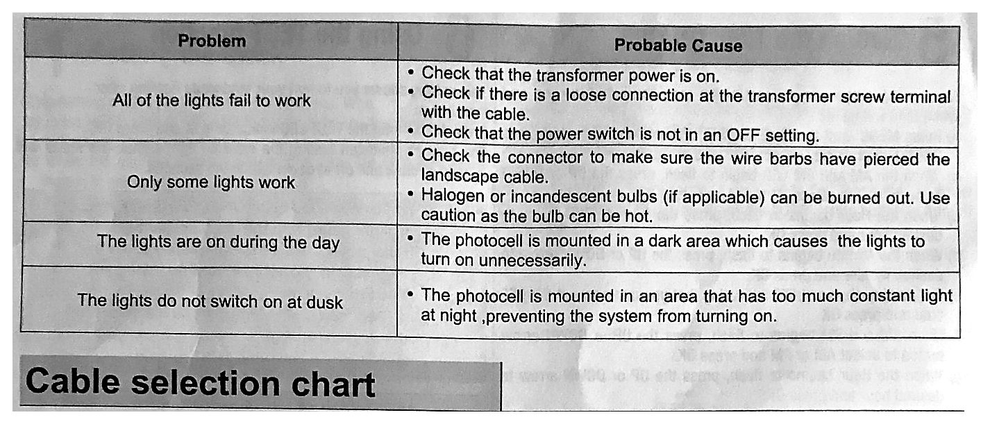
All lights fail to work
Check whether:
- transformer power is available
- the landscape cable is secure at the transformer terminals
- the operating control is in an OFF condition
Only some lights work
Check whether:
- the fixture connector has pierced and contacted the landscape cable correctly
- an individual replaceable lamp, where applicable, has failed
Lights are on during the day
The photocell may be mounted in a location that is too dark.
Lights do not switch on at dusk
The photocell may be receiving too much continuous nighttime light.
Overload protection
The Quick Reference Guide describes a resettable overload breaker at the bottom of the transformer. If the transformer trips, investigate the cause of the overload before repeatedly resetting it.
Warranty and manufacturer information
The photographed transformer documentation states a two-year warranty from the original purchase date for defects in materials and workmanship under normal use and service, subject to the exclusions in the original warranty.
The photographed material lists:
- Hampton Bay customer service:
1-855-HD-HAMPTON HamptonBay.com
Because the documentation may be older, verify current support information before relying on the printed hours or warranty process.
Church-specific installation record
Complete this section as the 2027 project becomes definite.
Project timing
- Tentative installation/use window: March–April 2027
- Final project date: To be determined
Transformer
- Exact model: To be identified
- Series: To be identified
- Rated capacity: To be identified from nameplate
- Installed location: To be documented
- Current/selected operating mode: To be documented
- Voltage tap: To be documented
Photocell
- Installed location: To be documented
- Orientation: To be documented
- Desired dusk turn-on behavior: To be documented
Cable
- Wire gauge: To be identified
- Approximate run length: To be measured or estimated
- Route: To be documented
- Burial/concealment method: To be documented
Fixtures
- Known fixture model:
IWH1501L-4PK - Number of fixtures actually used: To be confirmed
- Any additional fixture models: To be identified
- Total connected load: To be calculated
Original source photographs
The working source set currently consists of:
IMG_E2403.JPEGIMG_E2404.JPEGIMG_E2406.JPEGIMG_E2409.JPEGIMG_E2411.JPEGIMG_E2413.JPEGIMG_E2416.JPEGIMG_E2417.JPEGIMG_E2418.JPEG
The full-page photographs should remain preserved separately from the cropped Guide illustrations.
Revision notes
- 2026-10-09: Initial source-grounded Guide drafted from nine photographed Hampton Bay source pages. Added cleaned diagram crops and recorded the tentative March–April 2027 church project window.